

PEPS Surface Milling
Advanced CADCAM Software Solutions For The Manufacturing Industry
PEPS Surface Milling is a leading 3D surface machining CAD/CAM system developed specifically with tool & die and mould manufacturers in mind. It offers an intuitive environment for the design and comprehensive programming of complex parts.
Features at a glance:
- Intuitive graphical user interface
- Extensive range of CAD interfaces; both for import and export
- Fully integrated CAD functionality
- Tool library with holders, cutting parameters and sister tooling
- Area clearance roughing and rest roughing toolpaths
- Adaptive roughing
- Flat surface machining of planar surfaces
- Complete list of finishing strategies; including Zigzag, Waterline, Profile, Radial, Spiral and Morph
- Rest machining of fine details
- Combined finishing using multiple strategies
- Tapered tools supported on all cycles
- Smooth point distribution, and smooth transitions
- Full gouge protection
- Toolpath verification and simulation
- Configurable postprocessors
- High speed machining
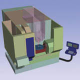
- Full Solid 3D machine simulation
Fully integrated CAD functionality. PEPS Surface Milling CAD module offers a powerful, fully functional CAD system with a large number of possibilities for constructing surfaces and solids. Solids can be created by adding or subtracting simple solid shapes or by more advanced techniques; such as, sweeping, extruding and lofting. Surfaces and solids can also be constructed from 2D drafting or 3D wireframe geometry. PEPS Surface Milling also has an extensive number of geometry modification tools that can be applied to either existing geometry or imported models; including repairing / removing holes and other features, creating constant / variable radius blends and adding draft angles.
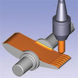
Tool library with holders, cutting parameters and sister tooling. Catalogues of tools, holders, extensions, adapters, feeds and speeds make it easy to keep control of and make use of the available tooling and utilise the optimum feeds and speeds. For long machining cycles, PEPS Surface Milling will keep track of the amount of machining completed with a tool. When the specified tool life has been reached the system will automatically call for a sister tool, minimising the risk of damage to the part being machined, by worn or broken tooling.
Area clearance roughing and rest roughing toolpaths. Ramp and helical entry paths with a spiral toolpath, smooth corner radii and smooth transitions between passes, will maintain the maximum feedrate on the machine tool, and prevent the cutter from dwelling in corners. For subsequent roughing operations, PEPS Surface Milling will remember where material is left on the component and only machine those areas. Wasted air cutting will be minimised and unnecessary rapid movements will be eliminated, while the cutter will avoid digging into areas where there is excess material, which could result in tool breakage. Where the starting billet is pre-machined, or is a casting, PEPS Surface Milling will recognise and machine only where material exists. Again this will eliminate wasted movement, and keep cycle times to a minimum.
Adaptive roughing. Adaptive Roughing eliminates full width cuts using a concept similar to trochoidal milling. This unique cutting technique provides the ability to cut using the full depth of the tool and safely run your machine at the optimum speed. Tool wear is spread evenly across the cutting surfaces and the centre of force is half-way up the tool, reducing deflection and the potential for vibration. Using Adaptive Roughing, the cycle automatically adjusts the toolpath for efficient and safe machining, improving cutting conditions and allowing higher machining speeds to be maintained. The most important benefits from this new strategy are that there is a reduction of up to 40% in machining time over conventional roughing (with less wear), the machine uses the full depth of the cutting tool, and the machine runs at the optimum speed without exceeding its limits at an isolated point.
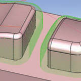
Flat surface machining of planar surfaces. For areas of the part which are flat, PEPS Surface Milling will automatically find these areas and machine them with a flat tool. The machining time for these areas will be significantly reduced, and also the surface finish will be greatly improved, by using a flat tool.
3D offset finishing toolpath. This toolpath provides a constant surface finish irrespective of the shape of the part. By morphing the toolpath across the surface of the component, one pass will finish the whole job, keeping the tool on the surface, minimising retract movements and eliminating duplicate cutter paths. Because the step over is smoothly adapted to the shape of the part, shock loading of the tool will be minimised, enabling the machine tool to run at high feedrates.
Radial finishing toolpath. For parts which are generally round, this toolpath provides a good method of finishing. Cutting upwards only, downwards only or zigzag makes it possible for the machining method to match the ideal cutting conditions for the tooling being used, while minimising unnecessary machine travel.
True spiral finish machining. By having one start point and one finish point, the spiral cutting path keeps the tool on the job, without any retract move in between. Tool loading remains constant as the tool does not make any sharp direction changes and the amount of material being removed always stays the same. This toolpath will enable the machine tool to run at very high feedrates as it will eliminate the acceleration and deceleration caused by sudden changes in direction.
Zigzag finishing. Unidirectional and zigzag paths can be applied at any angle to suit the shape of the part. If the shape of the component has some steep areas, limits can be set to skip machining above a specified angle, ensuring that cutter paths, which would cause a poor finish are not created. To cut the complete part in one operation the user can specify optimised cross machining. This automatically creates additional toolpaths at 90 degrees to the original toolpaths, cutting only where necessary to produce a constant surface finish across the whole component.
Waterline finishing. For parts, which have steep walls cutting in Z slices provides a good surface finish. Adaptive Z steps help to maintain a constant surface finish where the angle of the wall changes, putting more Z passes in where the wall angle gets shallower. Angle limitation can be applied to force the system to skip machining on very shallow areas, where a poor surface finish might be expected. To further improve the quality of finish, Z transitions can be by helical movements to keep the tool on the job and eliminate machining marks where the tool enters the material.
Morph finishing and Profile finishing. The user can control the cutting area by machining between two leading curves across a model. Parallel and perpendicular toolpaths give a choice of cutting directions, allowing more control of the machining method. A Profile can be created in space, on the surface of the model or a 2D curve may be projected onto the model. Machining the curve in space forces the cutter to run along the Profile, which is ideal for scribe lines. For projected curves, patterns and text can be engraved into the surface of the model by attaching the cutter to the curve and the surface.
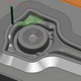
Rest machining of fine details. Small features on a model will usually require machining again with a smaller tool to completely finish the part. The rest machining command will reliably detect details left by previous tools, so that they can be re-machined. For very fine details, this process can be repeated as many times as required to make it possible to successfully machine with very small cutters. The toolpath can work from the outside to the centre or from the centre to the outside of small blends. For features, which are very close together, the toolpath will morph and blend together around obstacles to provide a smooth and flowing path without any sudden direction changes. The features in rest machining, which provide smooth tool movement and which minimise the number of retract movements all help to eliminate shock loading on the tool and keep feedrates as high as possible.
Combined finishing. Combined finishing allows the machining of Steep areas and Shallow areas using different machining strategies. This is a 'one-step' finishing routine. Using this strategy, it is possible to finish machine very complex parts using only one operation. It is possible to define an angle to split the Steep areas from the Shallow areas and select different machining strategies for each zone.
Tapered tools supported on all cycles. Where models have no draft, it is possible to use a tapered tool to machine draft directly onto the model. Straight tooling will require modification of the model to add the correct draft before machining can start. Adding draft to an imported model can sometimes be very difficult and time consuming for complex parts.
Smooth point distribution, and smooth transitions. As PEPS Surface Milling creates each toolpath it ensures that there is an even distribution of co-ordinates. By sending a smoothed CNC code to the machine tool control, it will reduce unnecessary acceleration and deceleration on the machine, making it possible for the machine to operate as close as possible to the programmed feedrate. All the toolpaths have smoothing radii in the corners, smooth transitions between passes and options for looping movements linking the ends of each pass. All these elements help the machine tool to run faster and prevent sudden direction changes, which would cause the machine tool to slow down and put excessive strain on the tool.
Full gouge protection. All the 3D toolpaths are checked against neighbouring surfaces to eliminate the possibility of the tool digging in. In addition small smoothing radii are automatically added to internal corners. These movements stop the tool from dwelling in the internal corners, which can cause the tool to be pulled into the job creating an unexpected gouge, which would not be detected by verification.
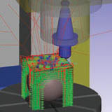
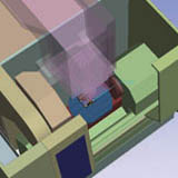
Toolpath verification and simulation. Checking the tool and the holder against the model provides a warning where there is going to be a collision, together with information about the length of tool required to complete the job. By limiting the Z cutting envelope for the tool, the programmer can use several tools to cut a cavity, taking advantage of the stiffness of shorter tools to remove most of the material. graphical verification of the completed toolpaths shows the sequence of operations and the surface finish. The cut part can be compared with the original model, to ensure that the part has been completely finished. Using visualisation helps to make sure the job is made right first time.
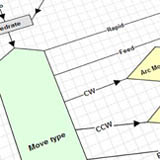
Configurable postprocessors. An extensive library of postprocessors is available to suit most machine tools. In addition postprocessors are fully configurable to suit individual requirements. Canned cycles for drilling and boring, subroutines to reduce program length, circular interpolation, cutter radius compensation, tool length compensation and handling of 3 + 2 axis machining all combine to produce CNC code which is easy to use on the shop floor.
High speed machining. The 3D toolpaths inside PEPS Surface Milling are designed to minimise the number of times the tool retracts, to keep the tool loading constant, to minimise sudden direction and speed changes, to avoid cutting into excess material, to smooth out the CNC code, and to eliminate tool collisions. Put together, this underlying technology makes it easy to successfully program high speed machine tools with PEPS Surface Milling.